A Dimension is a numerical value expressed in appropriate units of measurement and used to define the size location orientation form or other geometric characteristics of a part. Engineering Working Drawings Basics Page 1 of 22 Engineering Working Drawings Basics Engineering graphics is an effective way of communicating technical ideas and it is an essential tool in engineering design where most of the design process is.
Engineering Drawing Chapter 07 Dimensioning
Looking at the drawing.

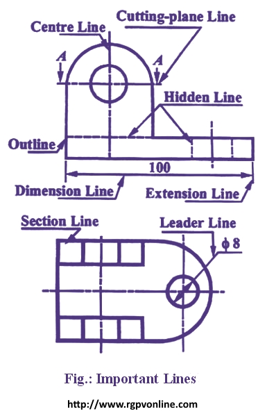
. A leader line consists of two parts. B Dimension lines show the direction and extent of dimension. This line is used to represent the center line for circles and arcs.
Looking at the drawing. Avoid chain dimensioning especially for mechanical objects. From any suitable portion of the reference note or number a short line is drawn parallel to the lettering.
13The primary unit of measurement for engineering drawings and design in the mechanical industries is the. Leaders are commonly used in technical drawings to show the required details. Leader Hatching type lines must be drawn thin and continuous.
A leader may also be used to indicate a note or comment about a specific area. Technical drawing Lines are used for different purposes to provide specific information for designers manufacturers etc. Make sure you understand the use of the viewing plane line to show an additional view.
For general engineering drawings the types of lines recommended by the Bureau of Indian Standards shown in table 2 must be used. Hold the pencil naturally. This line is used to represent the location of a cutting plane.
The following chart shows technical drawing lines that describe a piece of machinery with a swinging arm. A leader is a thin line used to connect a dimension with a particular area figure 24. They are preferably drawn at a 45 angles.
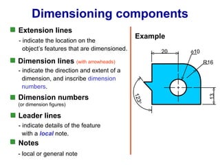
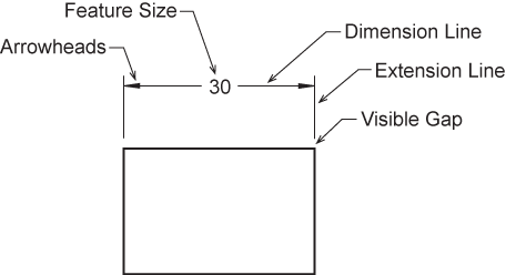
Spot the beginning and end points. A Extension lines are used to indicate the extension of an edge or point to a location outside the part outline. Extension lines begin 15 mm from the object and extend 3 mm from the last dimension line.
Vi Leader Lines A leader or a pointer is a thin continuous line connecting a note or a dimension figure with the feature to which it applies. PHANTOM LINE Long line followed by two short dashes use to show alternate position of a moving part. Leaders are solid thin lines drawn on technical drawings.
C Continuous thin wavy line. The Bureau of Indian Standards has prescribed the types of lines in its code IS-10714-1983 to be used for making a general engineering drawing. Engineering Drawing An engineering drawing is a precise technical graphic model that communicates design intent.
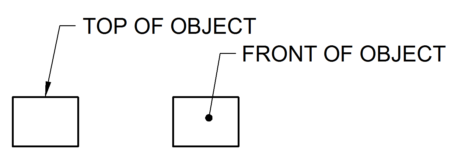
It is used by. Types of Lines The basis of any drawing is a line. This can be a dot if the line ends within the outline of the part an arrow if the line touches the outline or centre line.
Leaders are used to connect numbers references or notes to the appropriate surfaces or lines on the drawing. Dimension Marking with Center Lines in Engineering Drawings. A leader line is a thin line on a design or blueprint that is used to connect a dimension line with a particular area or point on the drawing.
SECTION LINE Medium lines drawn at 45 degrees use to show interior view of solid areas of cutting plane line. Leaders are more thin lines used to point to an area of a drawing requiring a note for explanation. A leader line is a line referring to some form of feature that could be a dimension an object or an outline.
C Leader lines are used to direct an expression in note form to the intended place on the drawing. This line is located in front of cutting planes outlines of adjacent parts censorial Lines and to state center of gravity. An extension line extends a line on the object to the dimension line.
Line types are also a language type to communicate between technical people. Avoid dimensioning to hidden lines wherever possible. LEADER LINE Medium line with arrowhead to show notes or label for size or special information about a feature.
But 30 o to 60 o is preferred. They are uniformly spaced about 1 mm to 2 mm apart. In the Alphabet of Lines thick dark lines represent the outline of an object showing its visible surfaces and edges.
A type B line thin continuous straight going from the instruction to the feature. Leader line Dash thick line Hidden. From this line the remainder of the leader is drawn at an angle dog leg to an arrowhead or dot.
Make sure you understand the use of the cutting plane line to show the section. One end of the leader terminates either in an arrowhead or a dot. This line is used to show hidden edges of the main object.
The Alphabet of Lines is a list of line symbols that engineers use in technical drawings to communicate specific shapes sizes or surfaces. Technical Drawing Line Types. Leader lines should be inclined between 15 o to 75 o.
These lines are drawn to make the section evident. Swing the pencil back and forth between the points barely touching the paper until the direction is clearly established. The thickness of the lines must be chosen according to the type and size of the drawing from any of the six groups given in Table 1.
If you are indicating a line on the part on the technical drawing start the leader with an arrowhead. In other words indicating on a drawing the sizes of the object and the other details essential for its construction and function using lines numerals symbols notes etc is called dimensioning. Table 1 shows the types and thickness of lines used for various purposes.
Leader line is drawn may be 30 or 60 to the bottom of dimensions. Sometimes leaders are used in place of extension and dimension lines especially when dimensioning arcs and circles. A Continuous thick line.
The first dimension line should be approximately 12 mm 06 in from the object. A 14To draw the leader line which type of the following line is used. Technical Drawing Line Types.
The use of a right type of line results in a correct drawing. The leader line should terminate in an arrowhead or dot. Draw the line firmly with a free and easy wrist-and-arm motion.
For general engineering drawings the types of lines recommended by the Bureau of Indian Standards shown in table 2 must be used. The most important rule of the leaders in technical drawings is that. The person who will read drawings have to learn what they mean.
Leader Line Leaders are more thin lines used to point to an area of a drawing requiring a note for explanation. All of the red bent arrow lines with notes are the leaders. B Long chain thin line.
Where a leader line is used to point towards the feature being dimensioned.
What Is The Use Of The Continuous Line In Engineering Drawing Quora

What Are Lines Types Of Lines In Engineering Drawing Youtube
Dimension Appearance And Technique

Engineering Drawing Dimensioning Part 1 Youtube
Draw The Following Lines Used In Projection I Extension Line Ii Leader Line Iii Construction Line न म नल ख त ल इन क ख च Solutions Ed Question Answer Collection

Extension Lines Drafting Joshua Nava Arts
Leader Lines Toolnotes

Dimension Guidelines Introduction To Engineering Design Ppt Download
0 comments
Post a Comment